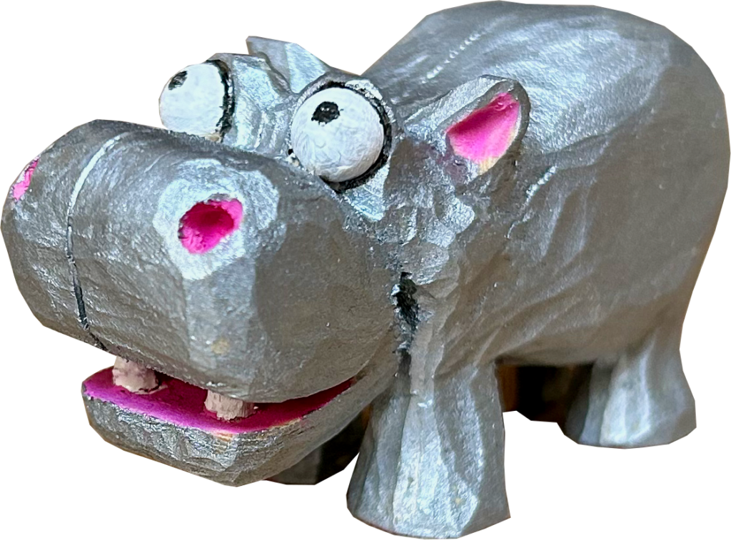
One day I woke up with an old song rattling around my brain with a merry chorus of “mud, mud, glorious mud…”. When I looked it up on Youtube I was reminded that it was actually called The Hippopotamus Song (https://www.youtube.com/watch?v=4zpDF3Py7r8). So of course I had to make a hippo. A hippo that might sing too.
The Design Brief
This is a very simple project which is mostly a carving job with the minor addition of a moving mouth.
Making
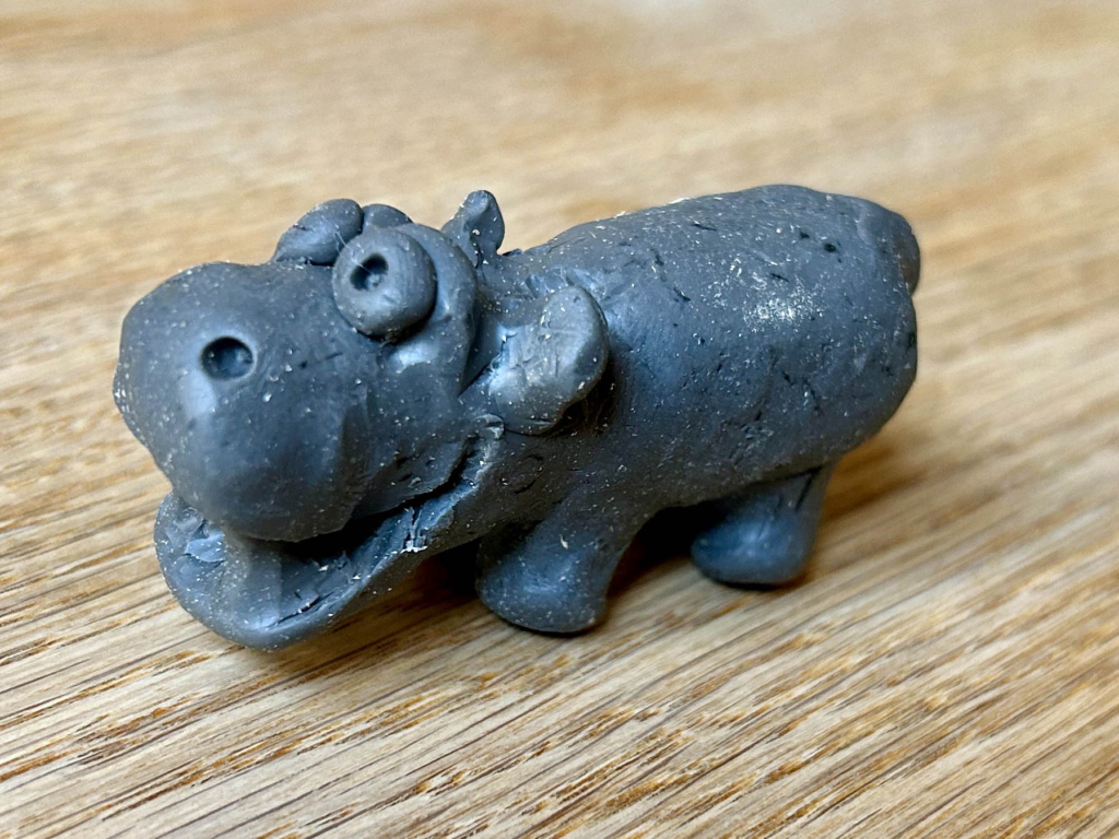
Before starting to carve I made a maquette in plastercine. The first thing that I noticed was that a large head is heavy and the whole thing tips forwards if the front legs are too far back. It’s always handy to discover things like that before investing a lot of work in carving. I have also decided that grey plastercine is very dull and I will choose something more cheerful next time I go shopping for plastercine.
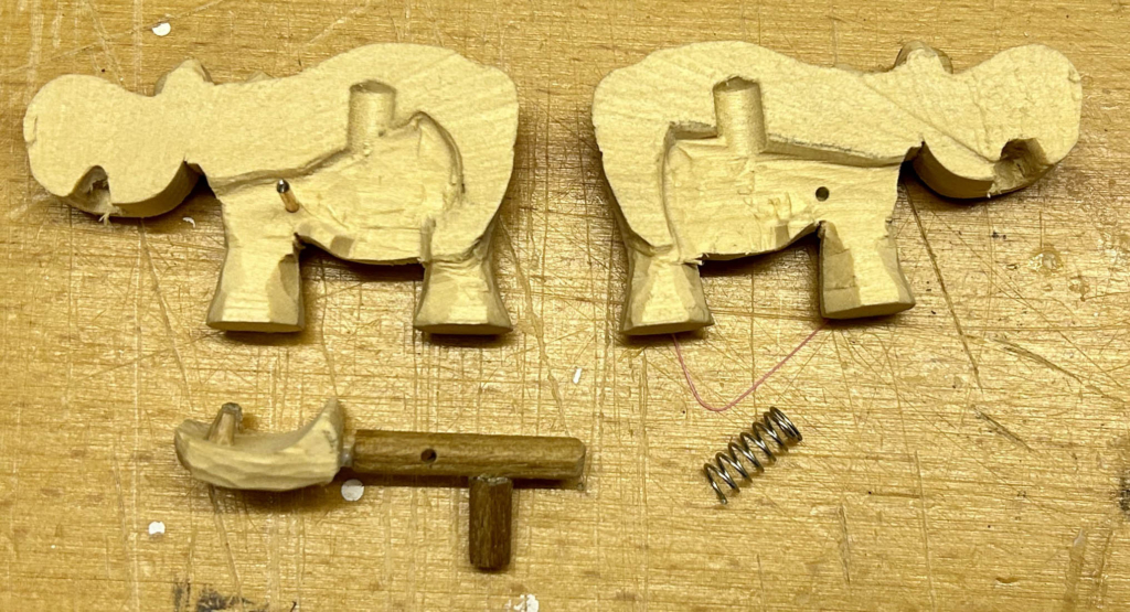
I carved the hippo in one piece, about 6 cm long, and only then cut the lower jaw out. This makes sure that the jaw will close nicely.
To be able to make space for the mechanism, I then cut the poor hippo in half.
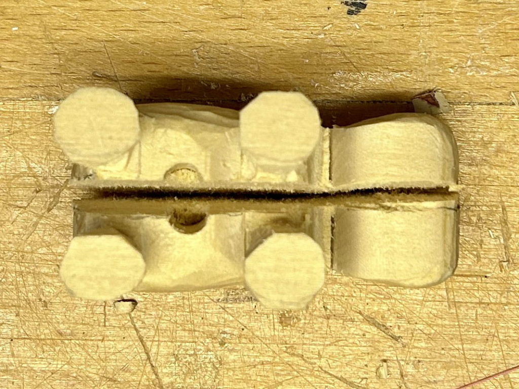
Inside the hippo, I had to make space for a spring and space for the lever to move. The axle on which the lever turns is simply a piece of brass rod. The lever is glued to the lower jaw.
With the lever in place you can see that I also made space for the teeth as the lower jaw comes up. You press the protruding part of the lever up to open the jaw. When you release the lever, the spring pushes the lever down to close the jaw. Once I was certain that everything moved easily, I glued the two halves together and got my paintbrushes out.
Reflections
The mechanism here is very simple and could be used to make all sorts of four-legged animals talk. As the operating lever is hidden underneath the body it’s not immediately obvious that anything moves. This adds to the surprise as you pick the figure up and demonstrate it to your latest visitor.
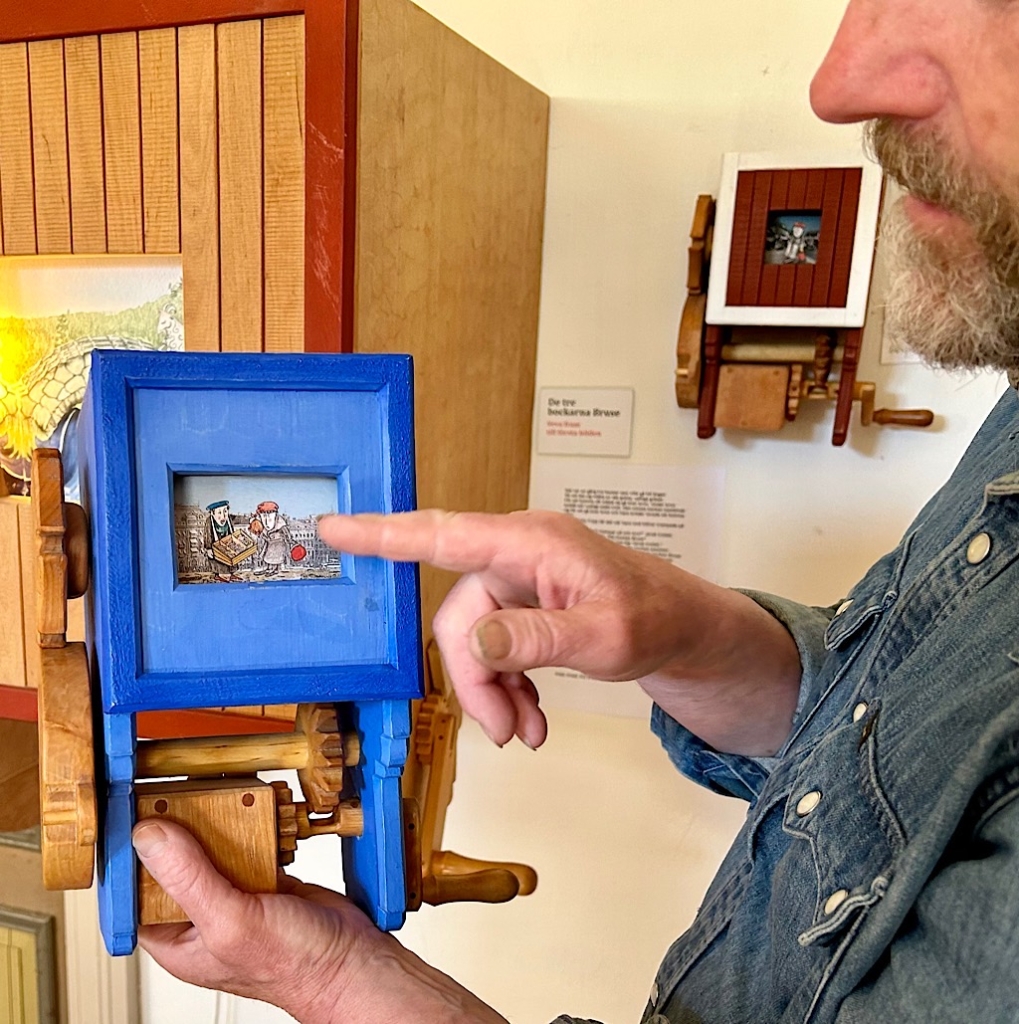
One day a video of an automaton made by Per Helldorff popped up on one of my Internet feeds. As Per explained when we eventually managed a visit, a previous visitor to his „mekaniske Kabinett“ made a video of his three-armed cup and ball trickster and quietly posted it onto YouTube (https://youtu.be/m9daxtL90XY?si=UqjMThCtTdzuSRQe) This went viral and, last time I looked, it had been viewed 1.3 million times. To his amazement, Per was then contacted by a Japanese TV network for permission to broadcast the video across Japan. He just wondered “how on earth did that happen?“
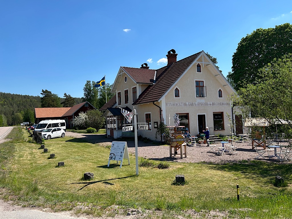
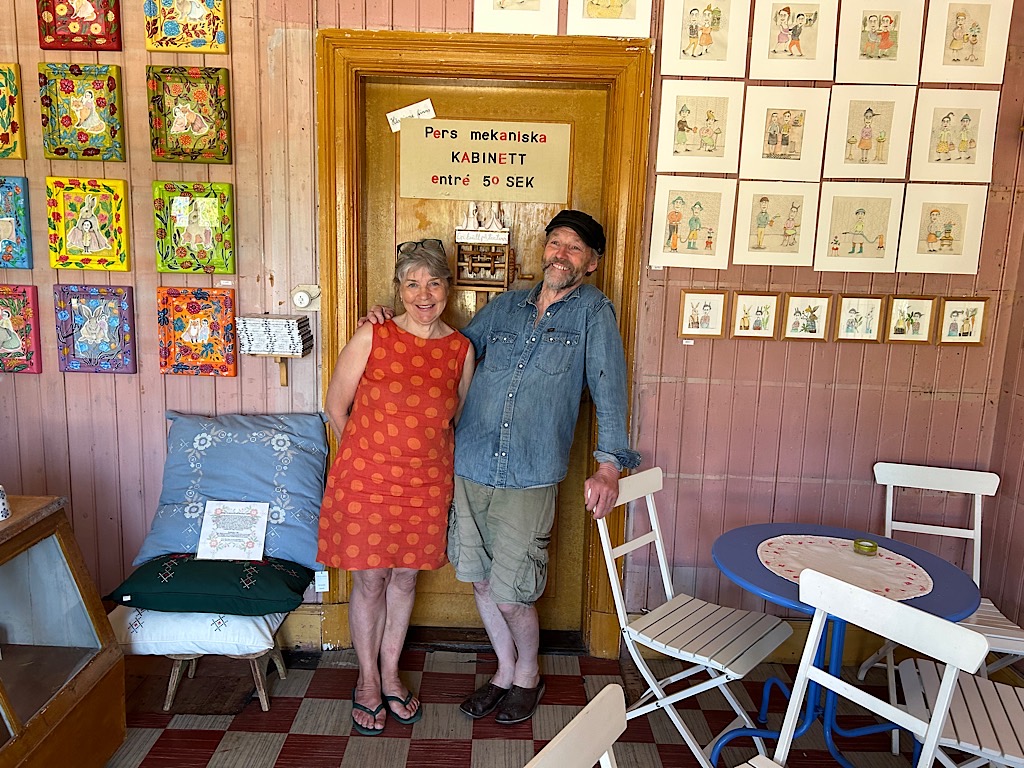
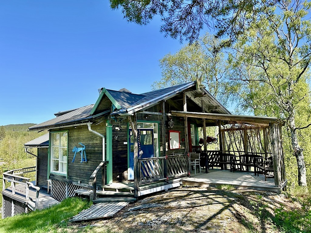
Per and his wife Anna live on a quiet crossroads in a tiny hamlet in the Swedish countryside. One room serves as the exhibition space and another as a small shop. Anna‘s nettle soup is legendary as one Swedish visitor told me – „we come here just for the soup“. We didn‘t come for the soup but to see Per‘s creations.
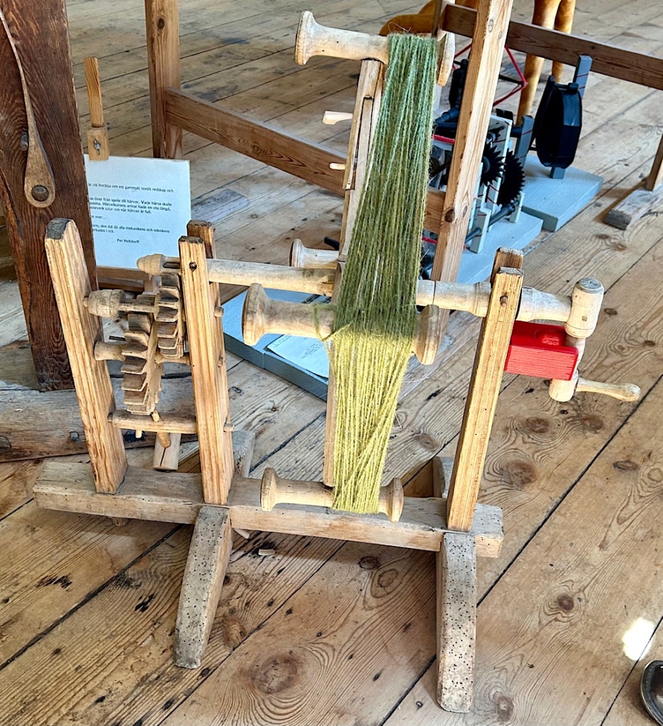
Per started by explaining his inspiration, showing us this historic wool skein counting machine. A woollen thread is wound onto the four arms as a handle is cranked. When the handle has been cranked a set number of times a wooden hammer hits the frame to signal that the required count has been reached. A royal Swedish edict from long ago specified severe punishment for anyone selling skeins of wool with less than the specified number of loops.
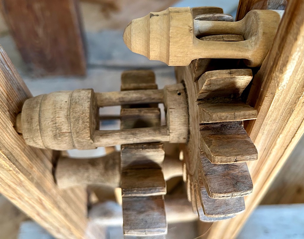
Looking closely at this old mechanism, two of the shafts have been carved to produce what Per called a „two-toothed cog“. This is a very pragmatic solution to slowly drive the large cogs. Using an „ordinary“ cog, a minimum of about 9 teeth is required to avoid the mechanism jamming. This traditional solution means that you can merrily work the crank on some of Per‘s automata and things happen at a considered, controlled pace.
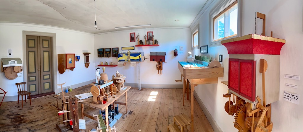
Anna and Per Helldorff at the entrance to Per’s mekaniske kabinettPart of the exhibition
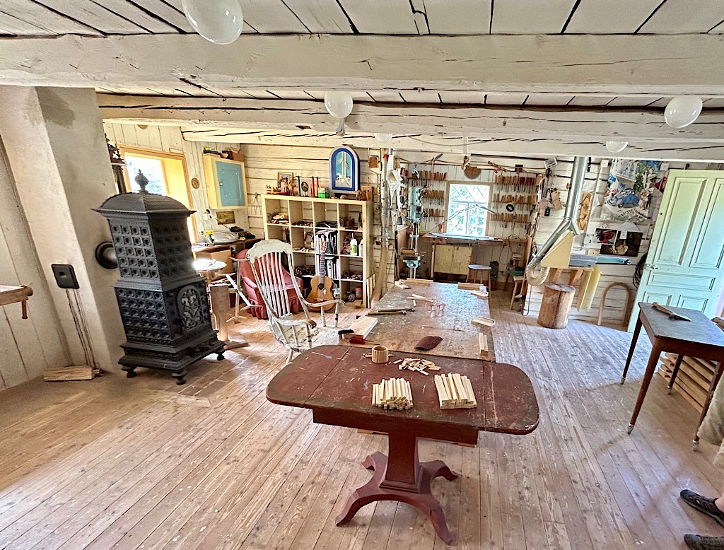
Per has worked with wood since he left school. He didn‘t receive any training, he just learned it all by doing it himself. Now of course he’s a skilled craftsman. When an injury restricted what he could manage, that was when he moved towards automata making. His sense of humour and creativity really distinguish his work. He doesn’t do drawings so, when someone orders an existing automaton, patience is required while he copies the original in his workshop.
I mentioned that I knew of no other automata makers in Sweden and Per asked if I knew of Tomas Skimutis. I hadn‘t heard of him so another visit was now on the cards.
A visit to Tomas Skimutis
Tomas Skimutis decided to build his own gallery. Was he a master carpenter? Well no, he wasn‘t he worked in graphic design.
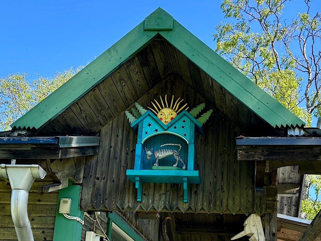
Over the entrance to Tomas Skimutis‘ gallery
Things were a bit chaotic inside as preparations were in full swing for a summer exhibition.
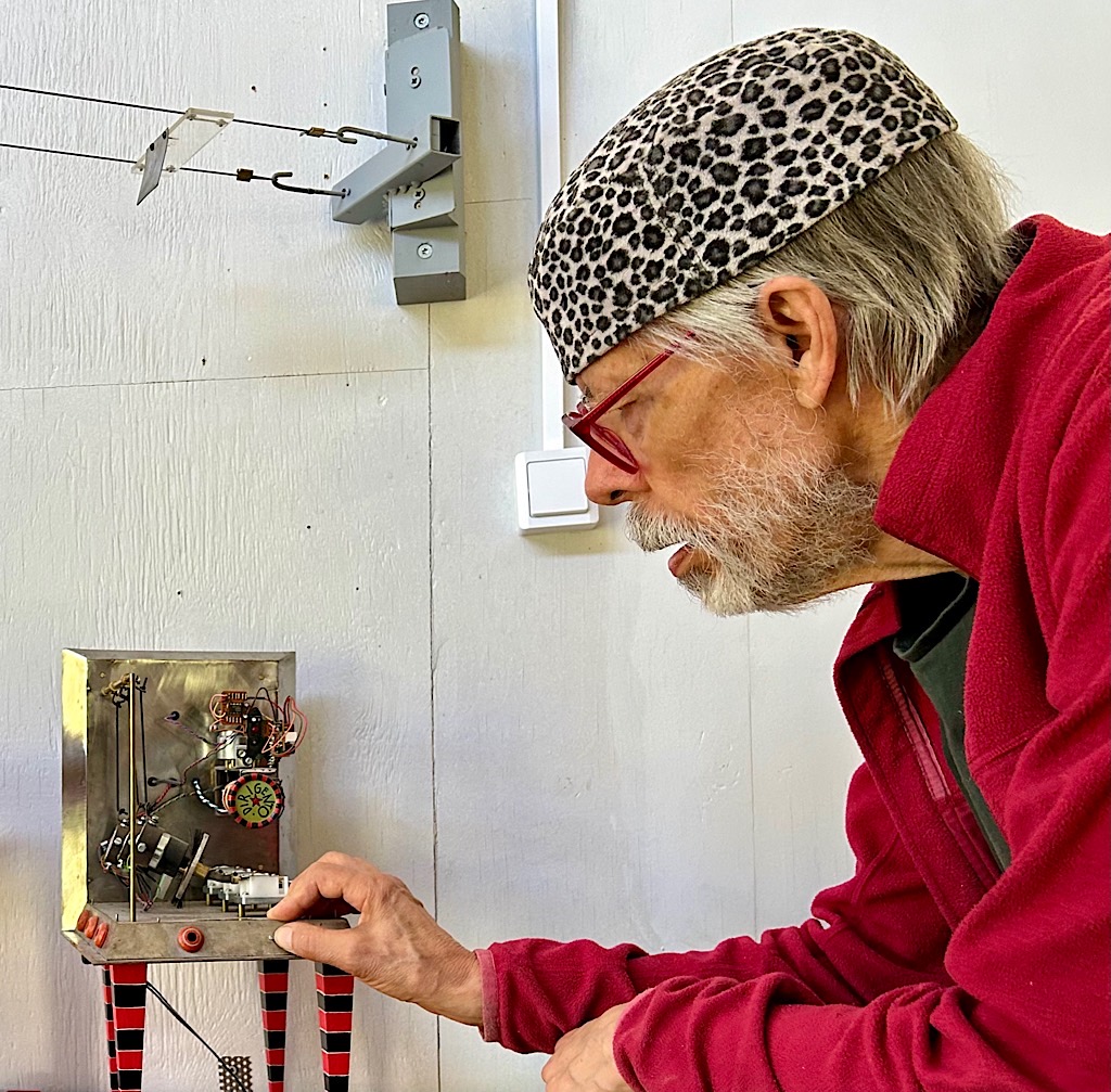
Tomas demonstrating one of his works
Still Tomas was happy to show us around. His projects are very varied including small pieces of furniture, occasionally including electrical/electronic bits and pieces, here and there with a handle to turn.
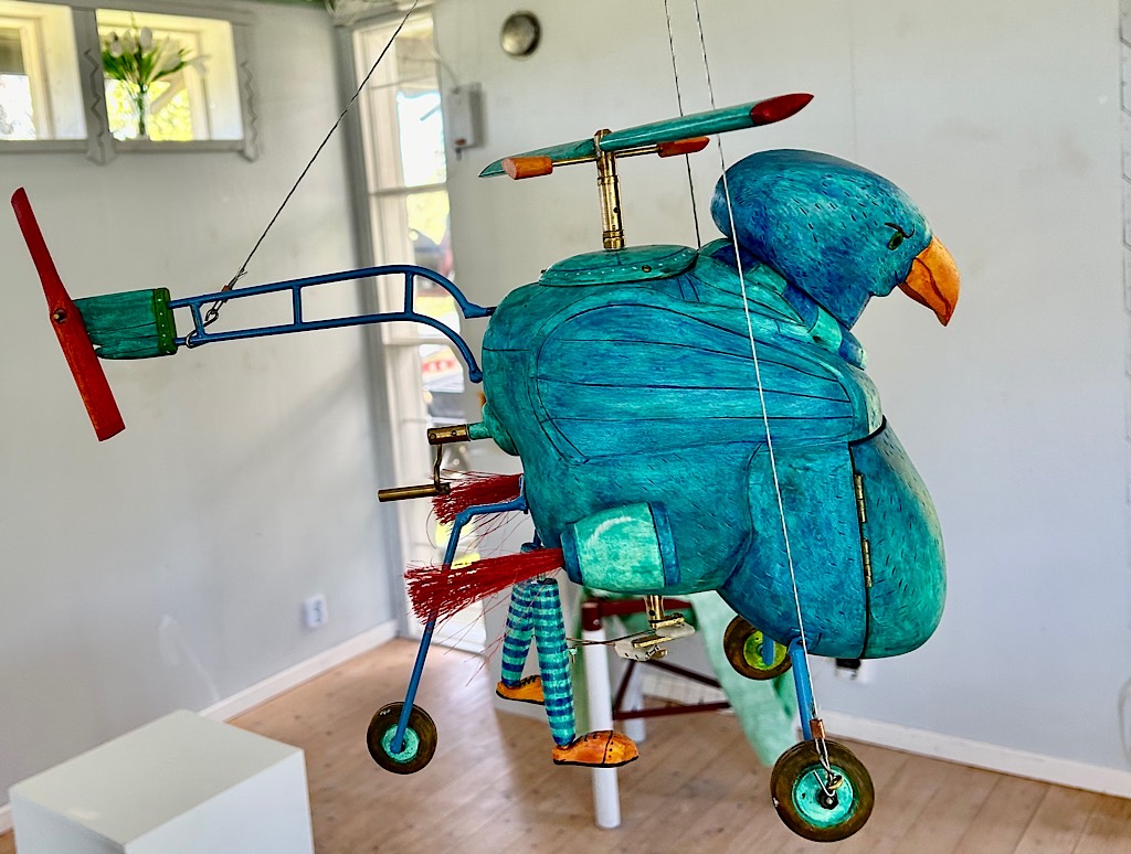
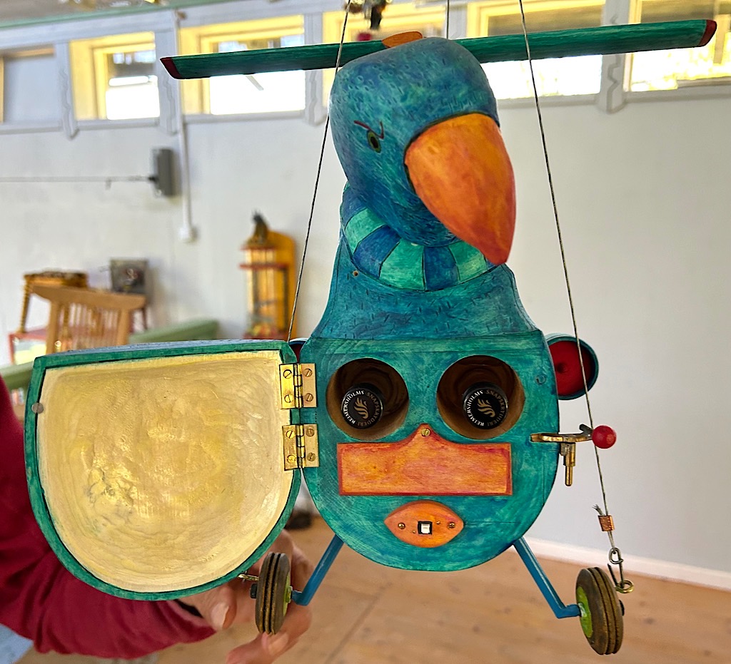
This bird-helicopter combination was a lot of fun. Tomas pushed a button to make it descend slowly down from the rafters. There is a crank to turn the helicopter blades, but you have to detach the lifting wires to allow the rotor to spin.
Opening the bird‘s chest reveals more secrets, such as the two small bottles of Swedish liquor stored inside. Not constrained by any rules or specifications, Tomas just added whatever he felt like and who can argue with that!
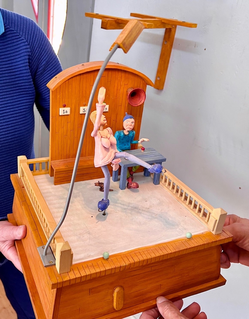
Another piece shows a contestant in a dancing competition twirling in front of a judge. This is hand-cranked but includes music from some sort of electronic player and some flashing lights to show the score.
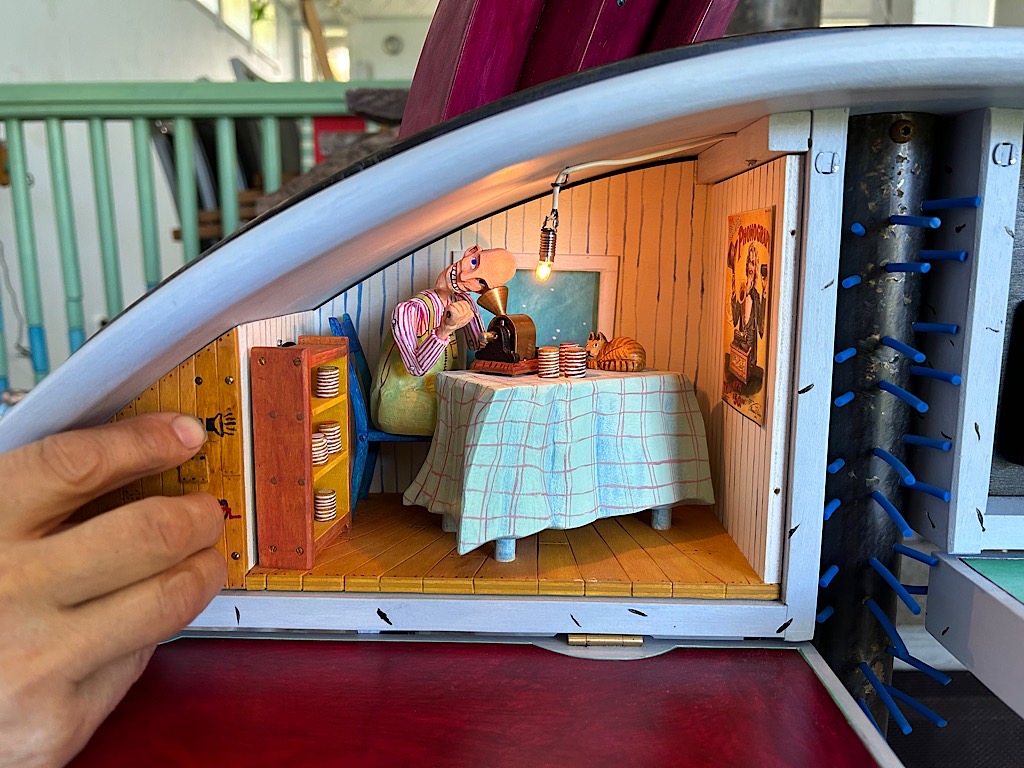
This detail from a much larger piece shows a man up in the attic listening to wax cylinder recordings. Pushing a button starts both the music and the movement of the man‘s arm as he cranks away.
As we had simply rolled up unannounced, although we saw quite a bit, a lot of things were not yet on display. Tomas promised that there would be lots more when his exhibition opens this summer 2024. If you can‘t make it, take a peek at the videos on this page http://www.skimutis.com/5/5.html and get ready to be amazed.
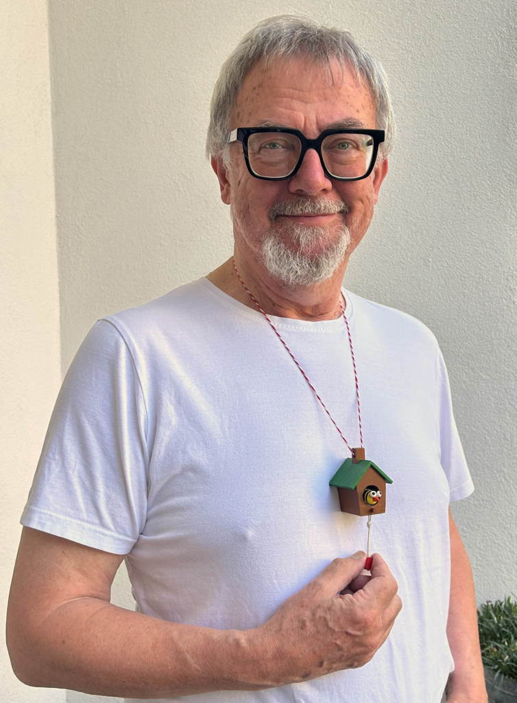
Recently I watched a video (https://www.youtube.com/watch?v=h_MHgkZKJGU) about the incredible Thomas Dambo building another giant troll in the forest near Rouen, France and I noticed that his troll is wearing a birdhouse around its neck. He explained that, when he was a rapper, he made necklaces with a little birdhouse for himself. “Great idea” I thought, I’ll pinch that and add some movement to make it my own. It is also coming up to birthday time for one of my friends so it will make a good present too!
A wearable automaton – who could ask for more?
A wearable automaton
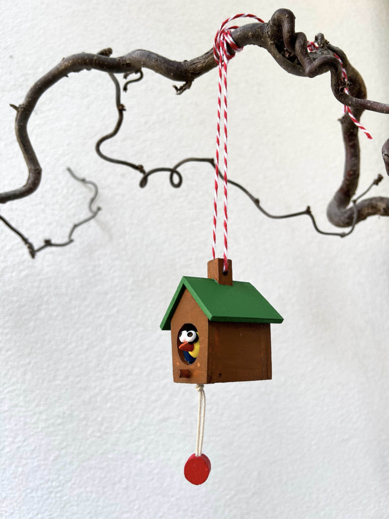
An automaton hanging from a branch
What’s the Story?
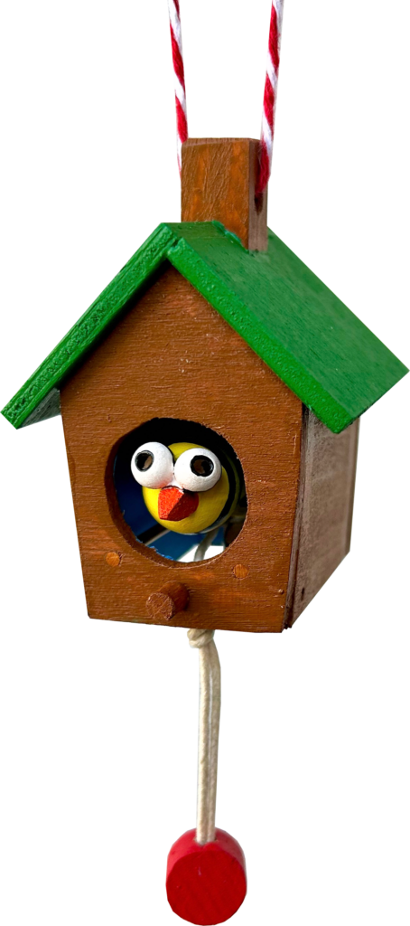
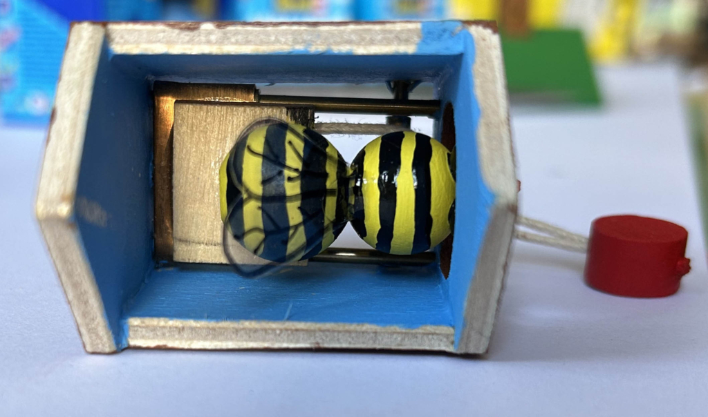
Just making something move isn’t that interesting, a story is required, even if it’s just a teensy weentsy one. You can see what looks like a cuckoo clock’s pendulum hanging at the bottom. Giving this a tug makes the occupant of my little house stick its beak out of the door. But is it really a beak? When the figure comes out, black and yellow stripes reveal it to be some sort of bee. First impressions can be deceptive.
So now I have a story – it’s a funny bee that is convinced that it is really a bird, a cuckoo. It has made itself at home in something reminiscent of a Bavarian cuckoo clock and, when the pendulum is pulled at the right time, it does its duty, pops out and, instead of “cuckoo” it goes “buzzz-buzz”.
Making
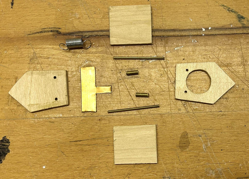
Some parts for the bee-house
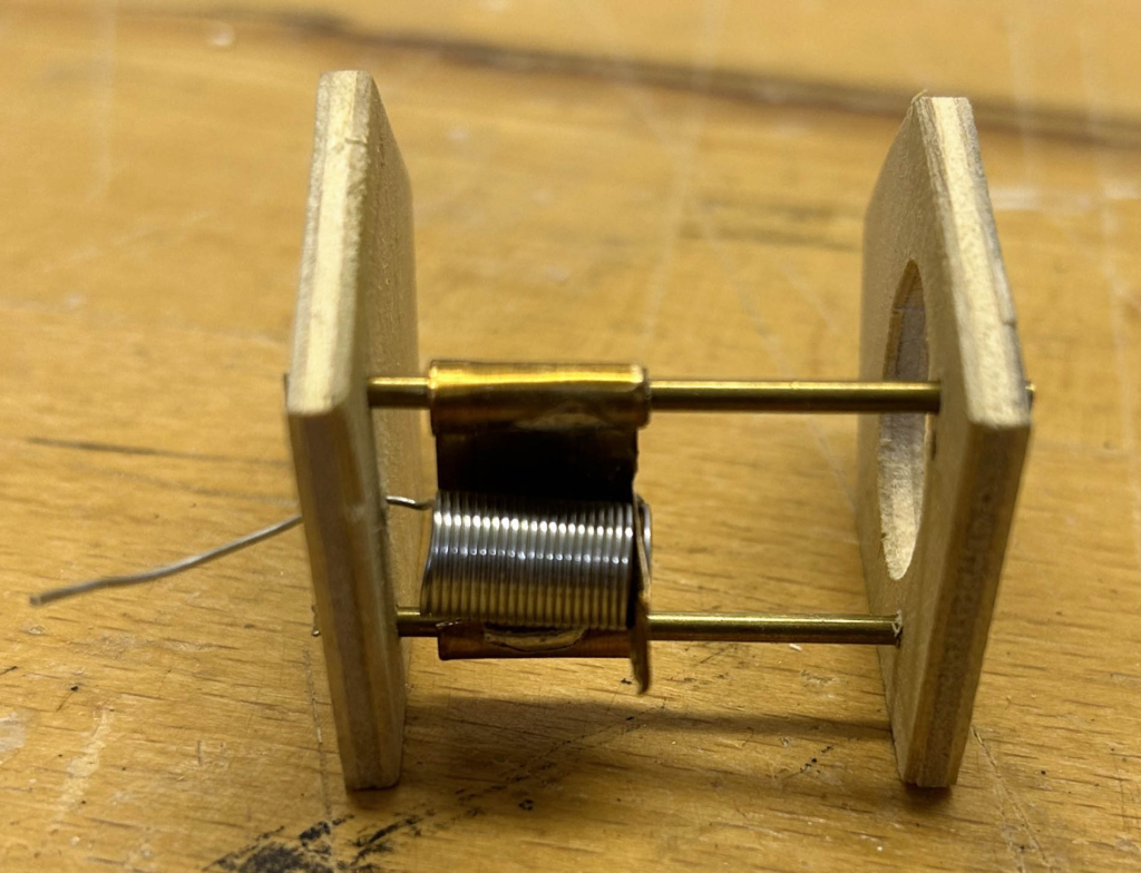
The house is made of 3 mm plywood, and stands 54 mm tall (not counting the chimney). To allow the movement forwards and backwards I used two brass rods along which two small pieces of brass tubing slide very easily. Some thin brass foil cuts easily to form a carriage which links the two tubes and holds one end of a spring.
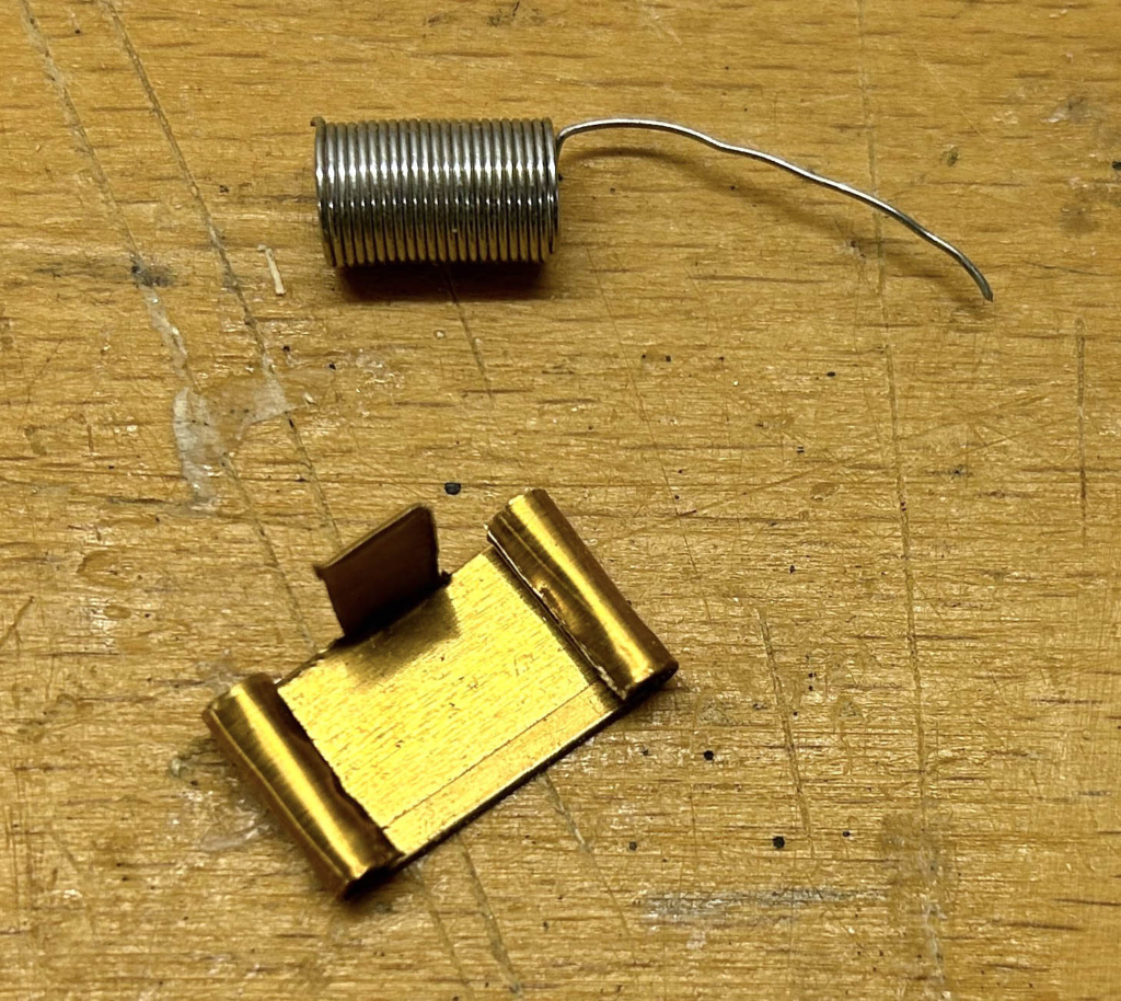
The metal foil carriage bent around two pieces of tubing, to be soldered together
The tab folded up 90° at the end of the carriage holds one end of the spring and soldering it in place makes sure that it stays put.
Carriage mounted on rods & spring soldered to the carriage
The “loose” end of the spring passes through a hole in the rear wall where it is glued (2-component epoxy resin) in place.
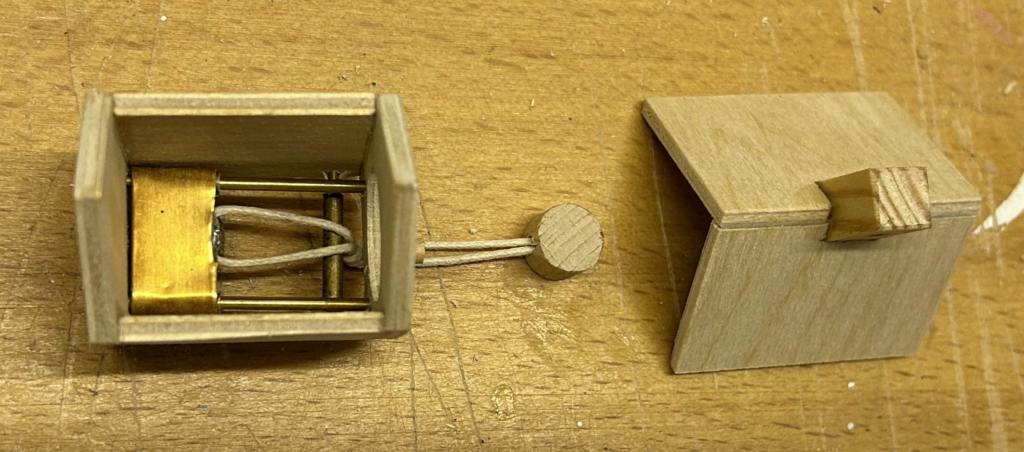
A roller for the pull string
To convert a downward pull into a forward movement a roller is handy. This is again made up of a solid brass rod with a loosely fitting tube slid onto it. I suppose that you could just use a plain rod, without a tube, but there would be more friction.
Note that the roof has a chimney in the middle. This is not just to keep things cosy inside, it also serves as a good place to thread a coloured cord through, to use as a necklace.
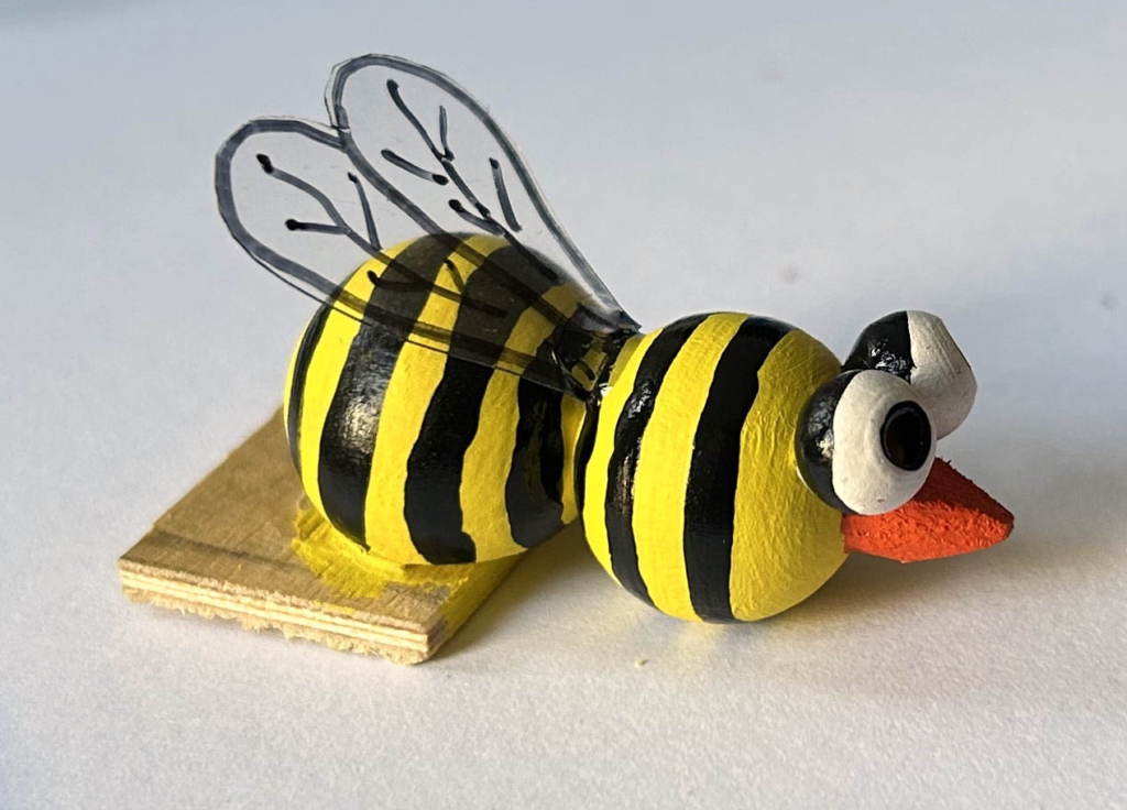
The bee ready to be glued to the carriage
The bee has to be fully painted before it is glued into the confines of its house. The wings are scarcely visible once installed, but what is a bee without any wings?
A top view of the bee now glued to the carriageThe open bottom showing the curious how it works
Soldering
Soldering is not hard. You need an electrically powered soldering iron and some solder. The very small parts concerned here don’t take long to heat up and to melt the solder until it flows along the surface. There is something called flux in solder which assists the soldering process. As the solder melts it produces quite acrid fumes which are best avoided or blown away from your nose/eyes. Things get hot of course, so try not to burn your fingers! Alternatively you could try glue, but make sure that it doesn’t get in the wrong places and gum up the movement.
Reflections
This is a relatively simple and quite small project and the motion is also fairly straightforward. If the viewer doesn’t immediately understand the story, some showmanship is helpful. Making the pull-cord swing to and fro while calling out “tick tock” reinforces the impression of a clock. When pulling the cord to make the bee reveal itself, a suitable musical “buzzzz buzz, buzzzz buzz” shows how the bee is doing its best to play the part of a cuckoo.
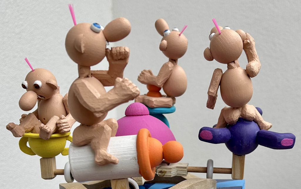
Some while back I visited Mirek and Leah at Puppets in Prague and I noticed this piece showing two parents and their baby. As you rock the cradle, the baby rolls contentedly from mum to dad to mum to dad… You could take another view and interpret it as the stressed parents shoving the responsibility for the squalling babe to and fro. Whichever way you look at it, I thought that it was a really interesting piece and that I should have a go myself. Mirek had no complaints when I suggested that, but my version has moved quite some way away from the simple elegance of his cradle.
What Interests a Baby?
Well apart from its parents, I came up with a short list including a milk bottle, a dummy (aka pacifier on the other side of the Atlantic), a potty and a soft toy. This gave me 4 options to play with, so I went for a carousel instead of a two-ended cradle. At first I thought that the babies could wear nappies, but then I realised that no self-respecting baby sits on a potty whilst wearing a nappy, so I put them all in their birthday suits instead.
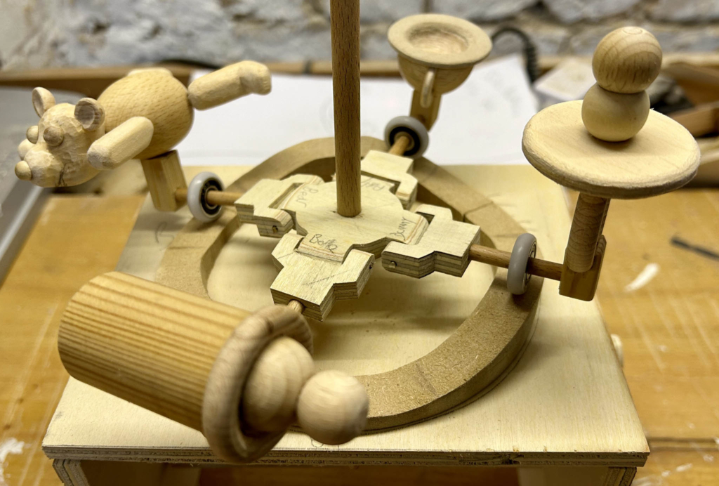
A potty, a milk bottle, a teddy bear and a dummy
Pinwheels
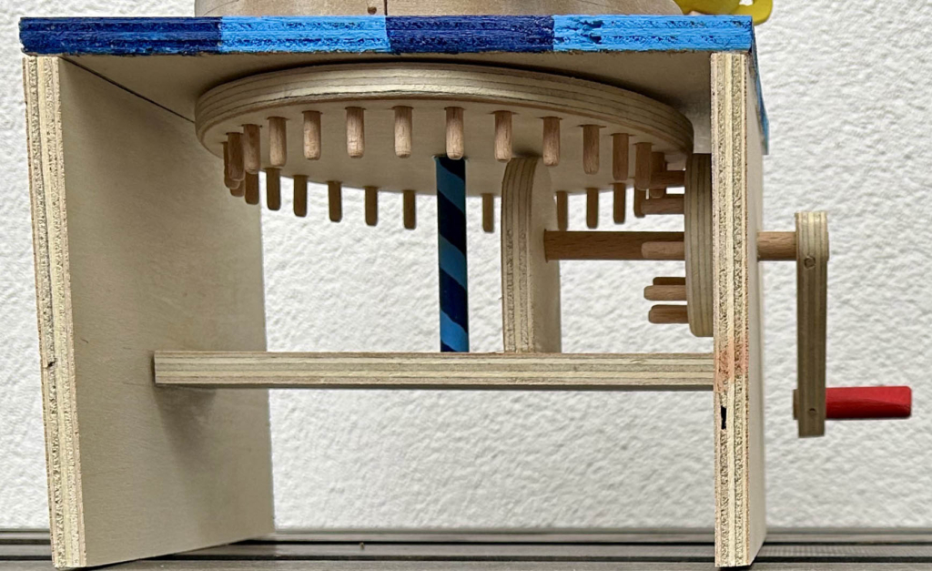
The pinwheels under the carousel
When someone turns the crank with its red handle, a 10-pin gearwheel turns and engages with a 30-pin gearwheel attached to the main driveshaft, painted with a spiral blue pattern. I used my favourite online wood gear generator (https://woodgears.ca/gear_cutting/template.html) with a pin spacing of 12 mm to print out paper patterns for the pinwheels. My pins are made of 3 mm dowel. Precision is very important here as the slightest pin-positioning error causes a grumbling noise as the pins engage with one another. My pinwheels usually grumble…
The Track
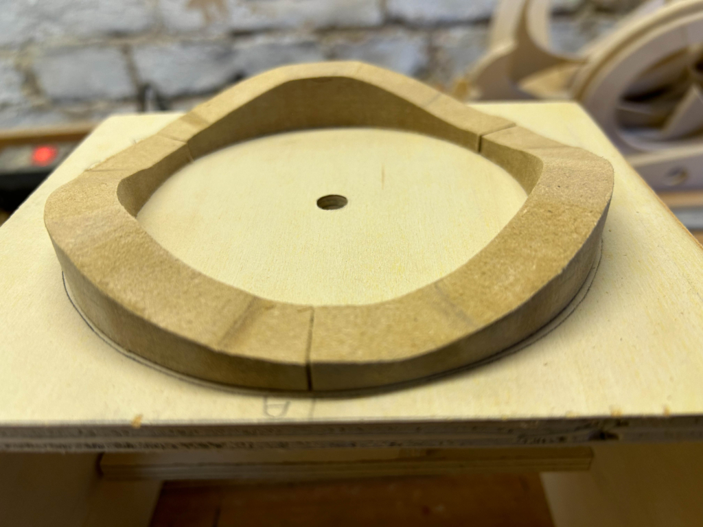
The up and down track
With some MDF (medium density fibreboard) I first cut a 20 mm thick ring shape for the carriage wheels to roll along. I pencilled a cutting line around the side with three peaks and troughs, to lift the carriages up and down. As MDF has no grain it’s fairly easy to cut a smooth curve. To avoid wear marks from the wheels, I didn’t paint it.
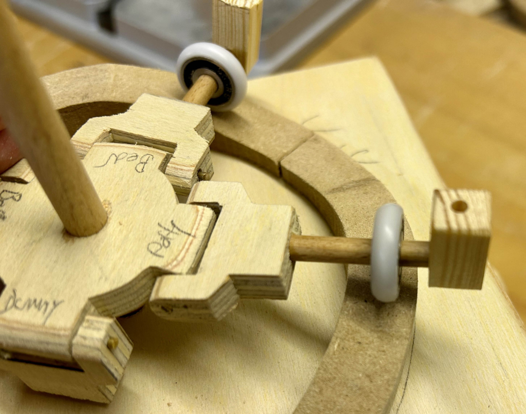
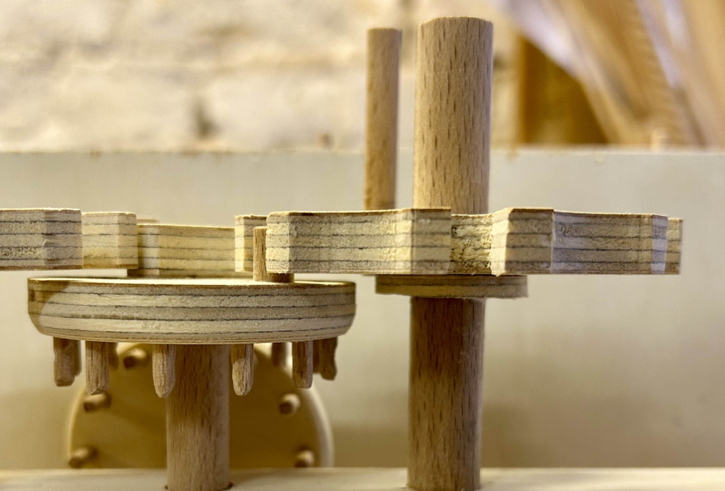
The Carriage Driver
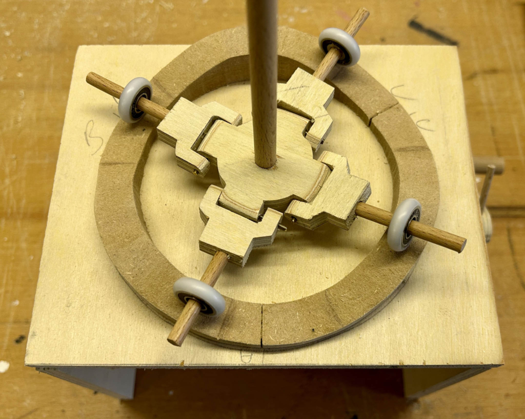
The mechanism to move the carriages
The shaft which is driven by the large pinwheel turns a “cross”. This cross has four stubby protrusions which each hinge an arm with a wheel. Each wheel runs along the track. I found the wheels (with ball bearings) in a dusty drawer somewhere. I must have bought them from a craft shop some time ago.
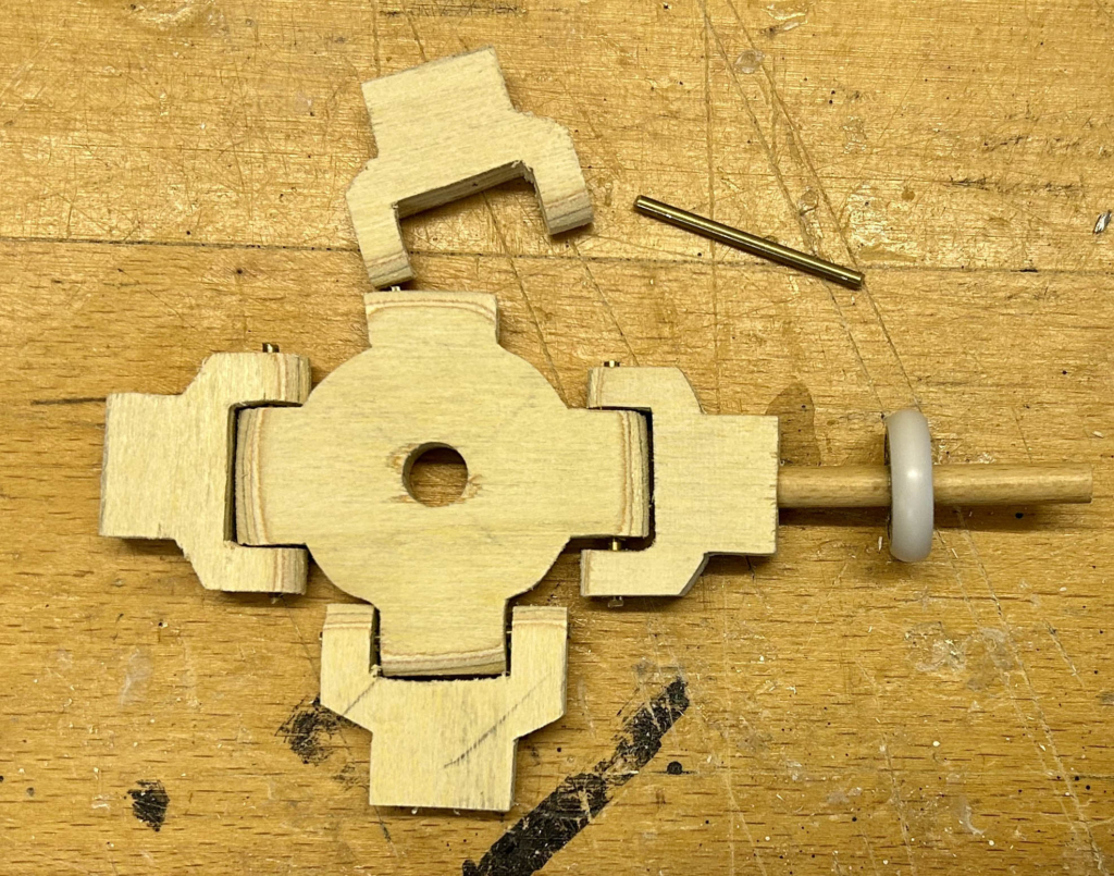
Hingeing the arms
The hinges use small pieces of brass rod which move freely in holes drilled in the central “cross”.
Block to mount the carriages
Each “carriage is mounted on to a small block at the end of its arm.
Four “carriages”
The four “carriages” are still without any passengers here.
The Passengers
I was unsure what posture the babies would take on their very individualistic carriages, so I decided to leave the decision as late as possible in the assembly process
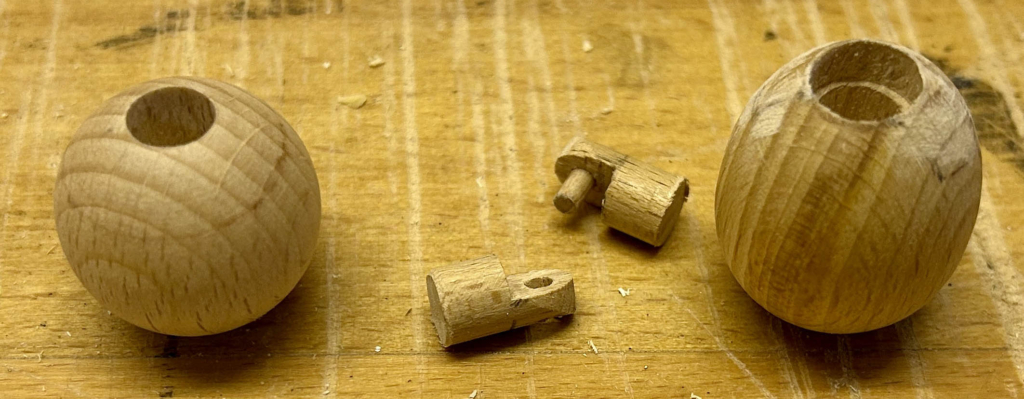
A head, a hinge and a body
A wooden ball serves as a head and an egg as the body. A very primitive hinge allows me to tip the head this way and that until I was happy with the pose and a dollop of glue fixes it for all eternity.
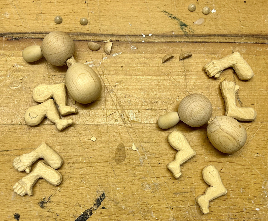
Baby bits
I carved arms and legs as separate entities. Only when I could see how each baby can sit on their carriage did I fetch the glue out.
Four babies, four postures
The babies on the milk bottle and the bear can sit astride, as if riding a horse. The baby on the dummy wraps its legs around the teat and hangs on to it for dear life. The last baby, on the potty, has half fallen in to the opening and is looking down in amazement, presumably at what it has just produced?
The Last Touch
The mechanism in the centre is of course a hazard for small fingers so I made a symbolic mum from a large wooden hemisphere to cover everything up, well almost everything.
On Reflection
There is not actually very much going on here. The main performers sit very still on their carriages. It’s a frozen tableau which just goes round and round and gently up and down. I suppose that a brand new observer will take a while to sort out what all of the various elements represent and recognition may result in a soft smile. The potty may be hard to recognise as it looks more like an antique chamber pot, so I added a reminder of what it might contain by painting it yellow. Whatever else, I will be quite content with a soft smile.
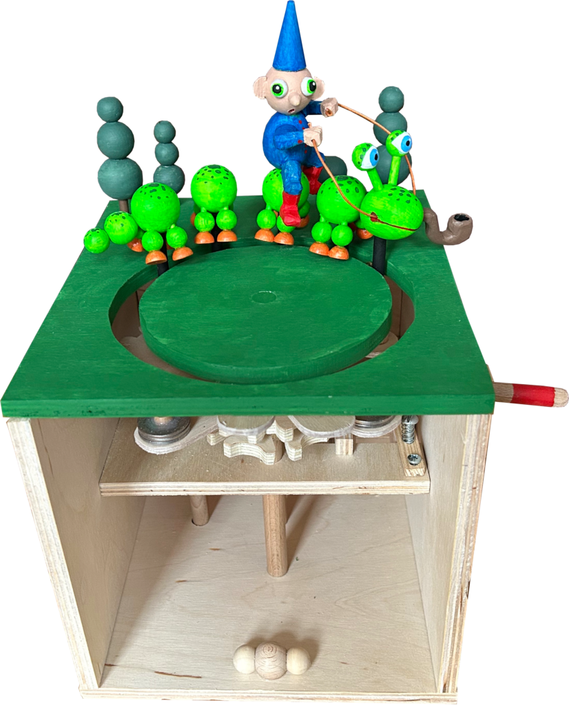
I find the Geneva mechanism quite intriguing, so I thought it was time that I had a go with it myself. My initial idea was to make something like an inchworm or a cabbage looper, where the animal humps its back to bring up its rear legs and then stretches out to move its front legs forward. However, I was worried about the force required to lift up the body, so I went for a caterpillar that alternately stretches and contracts its body to move. A small passenger adds a little absurdity and I borrowed an idea from Lewis Carrol’s Alice in Wonderland where his caterpillar smoked a hookah. Mine smokes the portable version, a pipe.
The Geneva Mechanism
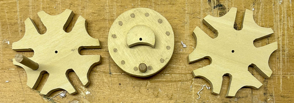
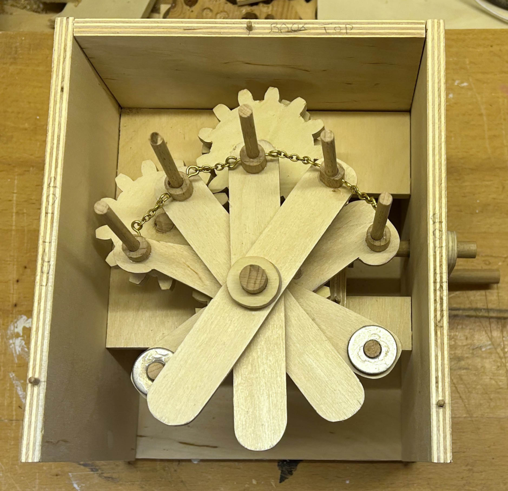
Parts for the dual Geneva mechanism
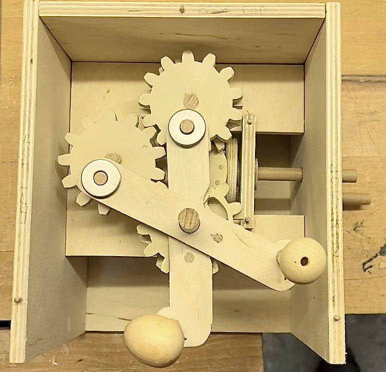
Searching the Internet, I found a marvellous Geneva Gear Generator https://benbrandt22.github.io/genevaGen/ which I used to produce a 6-way Geneva wheel design. From this, I made two wheels and the central driving element which is mounted onto the back of a pin gear with 12 pins.
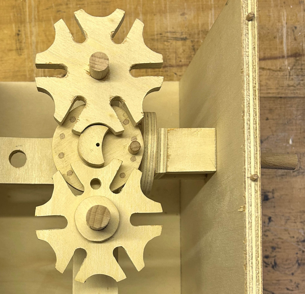
Prototype assembly of dual Geneva mechanism
The hand-turned axle drives another pin-wheel which engages with the central driving element. As the axle is turned the element rotates and turns the two Geneva wheels one after the other. Later on I found that misalignment occasionally occurred, jamming the movement. I fixed this by rounding off the corners where the round dowel on the driving element enters the long slots in the wheels.
Spacing the Geneva parts
To prevent friction from driving the wheels instead of the small piece of protruding dowel in the central element, the Geneva wheels must not rest on the central element, so I glued a wooden washer in place underneath each wheel allowing the wheels to turn freely when required.
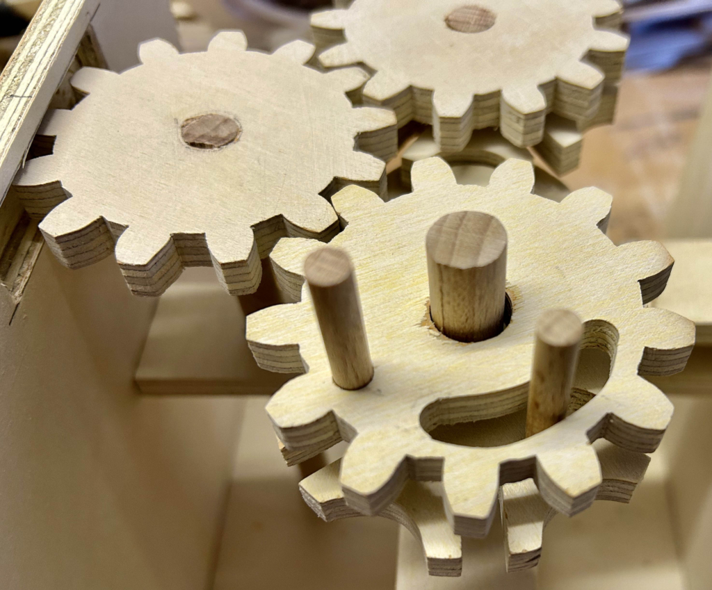
One Geneva wheel directly moves the front of the caterpillar via a piece of vertical dowel. The second wheel drives the caterpillar’s tail via three cogs and another piece of vertical dowel. I designed the cogs using another online tool https://woodgears.ca/gear_cutting/template.html.
Three cogs to move the rear part of the caterpillar
The first cog is glued to the top of its Geneva wheel. The third cog turns freely above the other Geneva wheel, not touching it at all. This cog has an opening to allow the dowel from the Geneva wheel underneath it to freely move through an arc driving the front of the caterpillar, while it has its own dowel to drive the rear of the caterpillar. The second cog links the first and third together.
Extension Arms
The arm to move the caterpillar’s head
To enlarge the diameter of the caterpillar’s movement, extension arms are required. These also allow some counterbalancing to keep things horizontal.
Two arms, with counterweights, for the caterpillar’s head and tail
With the caterpillar’s head and tail now alternately driven, there is a sort of scissoring action which first pulls the head away from the tail and then pushes the tail towards the head.
Five arms for five caterpillar segments
Three more arms are needed for the three segments between the head and the tail. The segments are linked together with a small piece of brass chain so that when the head moves it can pull the other segments along behind it.
A Ratchet
The ratchet
I didn’t want the caterpillar moving backwards, so I added a ratchet onto the drive shaft to prevent the crank from being turned the “wrong” way. Tightening the longer screw compresses the spring and makes things quite loud. I adjusted it until it did what I wanted without making too much of a racket.
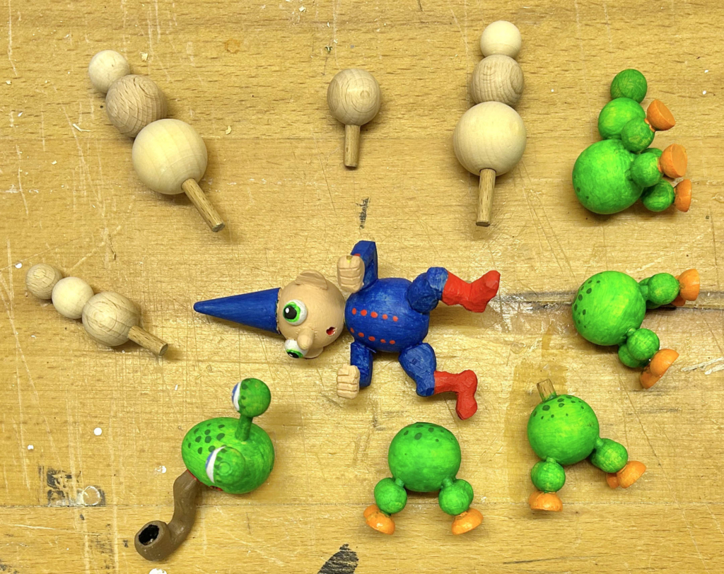
The Caterpillar Segments
Caterpillar segments, trees and the rider
The caterpillar segments mostly comprise wooden balls, with a wooden egg for the head. A few trees round off our small scene.
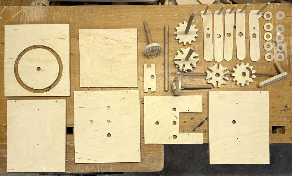
Making
Most of the parts
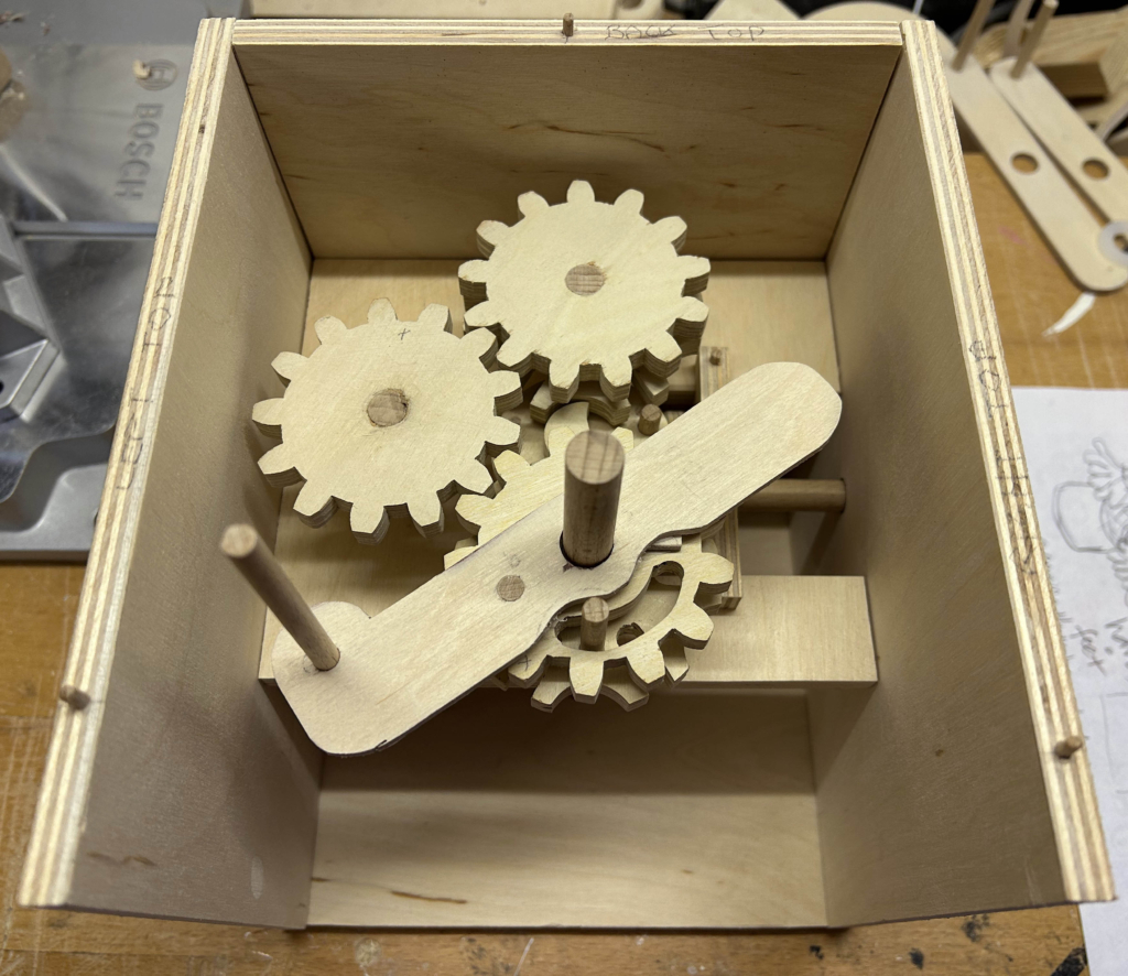
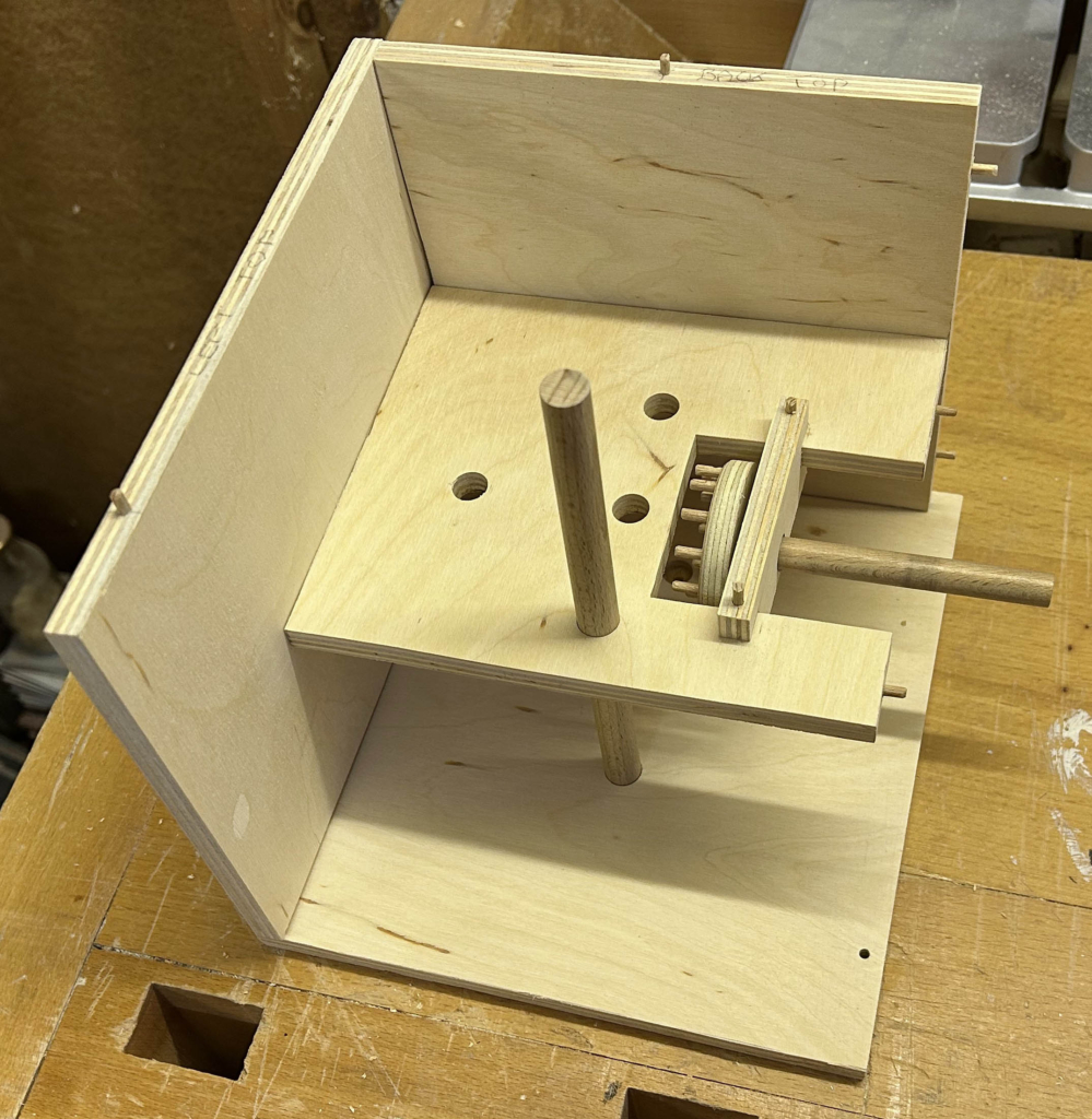
This project is more complex than a lot of my automata, but there aren’t really that many parts to it. I used slightly thicker plywood than usual to improve rigidity and precision. During the first assembly, I noticed that my box was too small, so I made a new, larger one and took the opportunity to tidy things up a bit.
The new box showing the pinwheel driven by the crank handle
Note that the 10 mm diameter vertical dowel, which you can see in the photo, is fixed and glued in place. It represents the centre axle for the main mechanism. It does not move itself, the parts and the caterpillar move around it. When fully assembled the green disc is glued flush to its top.
Too Complicated?
Before I started, I looked around the Internet to see if anyone else had made a caterpillar automaton, I bumped into https://makerworld.com/de/models/468733#profileId-377949. This is a project for a 3D printer and, on the face of it, looks a lot simpler than mine. I don’t know whether it would work well, when made by hand in wood. What do you think?
Still, I am very pleased with how my project turned out, it works reliably and entertains my friends large and small. It took a while to make, but that’s part of the fun in making automata, overcoming difficulties and learning more every happy hour that I spend working with my hands.
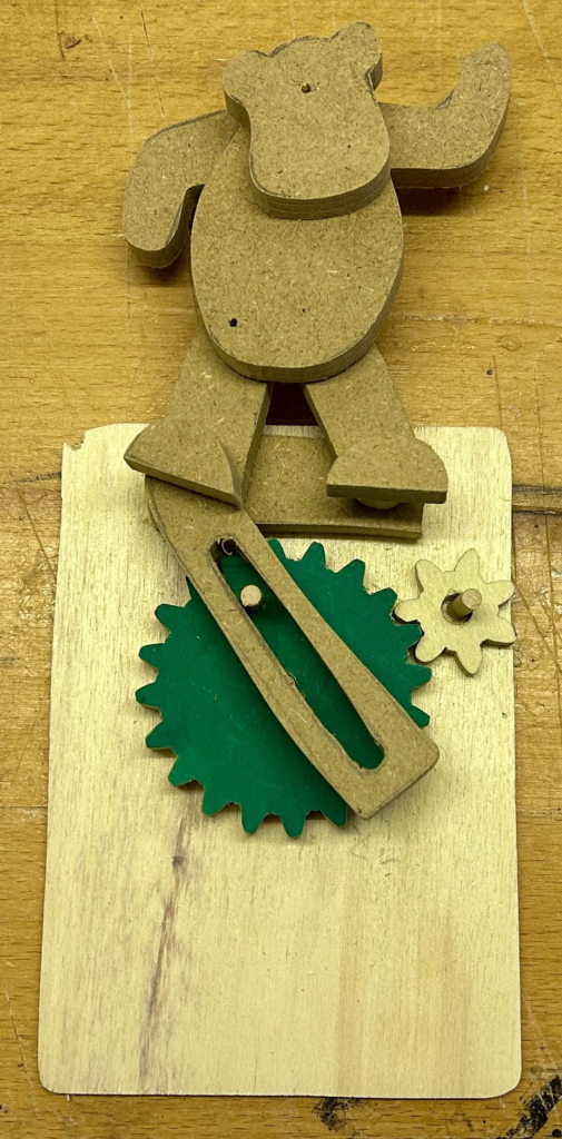
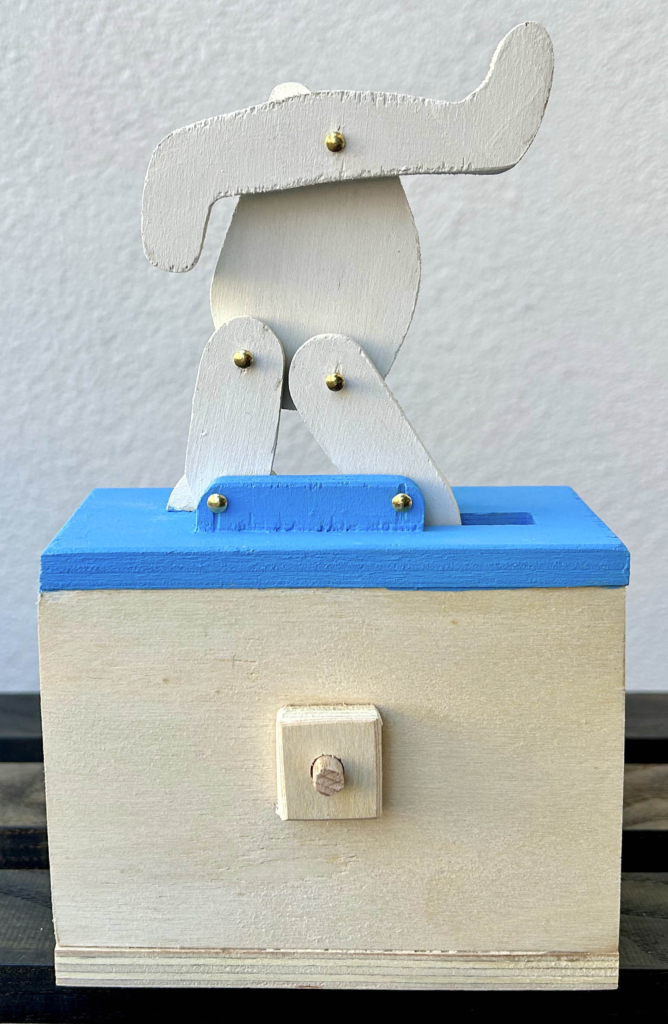
I have often admired Peter Markey’s Guitar and dancer (https://cabaret.co.uk/artists/peter-markey/) and thought “I’ll have a go at that” but with my own particular twist. At some point, the dancer became a bear but that was OK, even if I did start humming that Louis Prima hit where Baloo the bear dances around as the monkey king Louis sings “I Wan’na Be like You” in The Jungle Book (https://www.youtube.com/watch?v=ud5J7Ye332I).
Approach – Just go for it
Aiming for a simple project, I abandoned the guitar player and concentrated on the dancing bear. I decided to just go for it and start making, without having a clear idea at the start of how it would work.
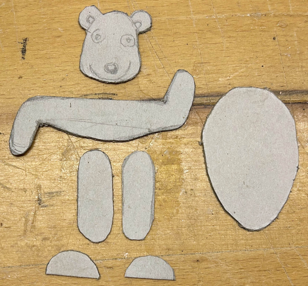
A cardboard bear
After sharpening a pencil, I drew myself a bear on a piece of paper and then reduced it to seven pieces which I copied onto a piece of cardboard and cut everything out.
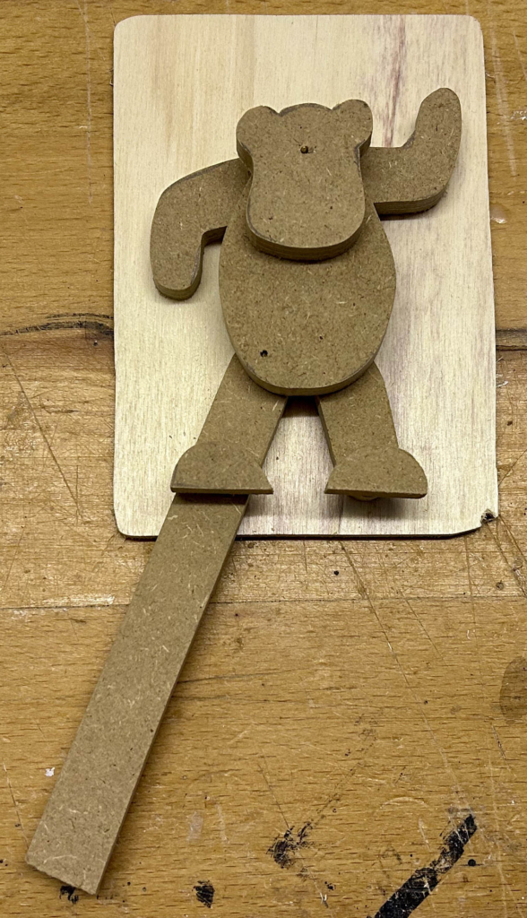
Down in the workshop, I used the cardboard templates to make prototype parts out of MDF.
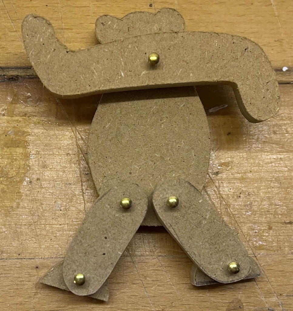
A prototype bear
Some 2 mm thick brass pins served well as hinges.
Prototype bear
I lengthened one leg to form a lever to get things moving.
Quick prototype assembly of the mechanism
To keep things small, I added a bend to the lengthened leg. I found a couple of cogs from an old abandoned project and fixed everything to a piece of scrap wood to check the movement.
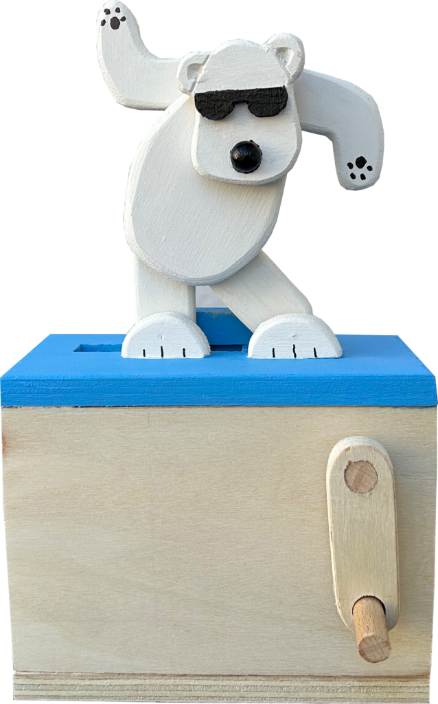
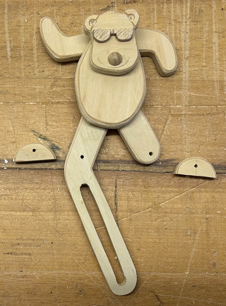
A bear made of 9 mm plywood
Once I was satisfied with the movement, I used the MDF parts as templates and cut out more robust copies in 9 mm thick plywood. MDF is cheap and quick to cut, but I don’t think that it’s sensible to make moving parts from it. Cool bears wear sunglasses of course.
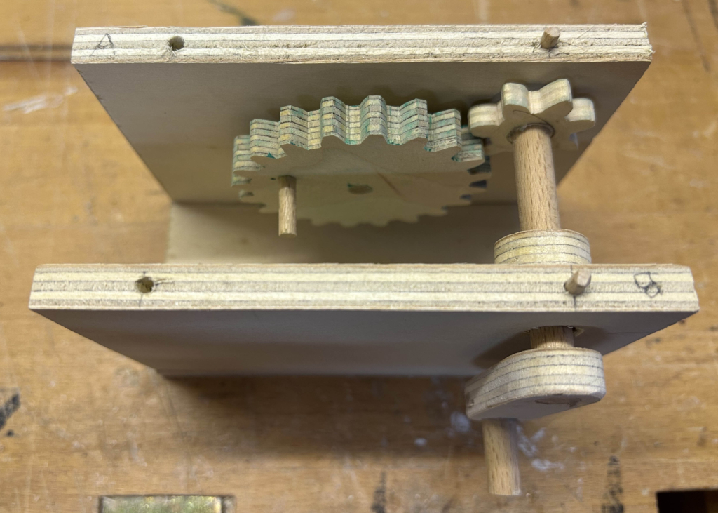
A base to hold the cogs
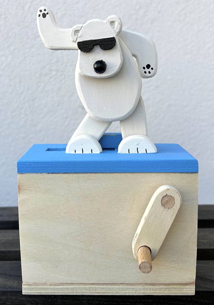
Taking the measurements from the prototype assembly, I made a box and added a crank to get things moving.
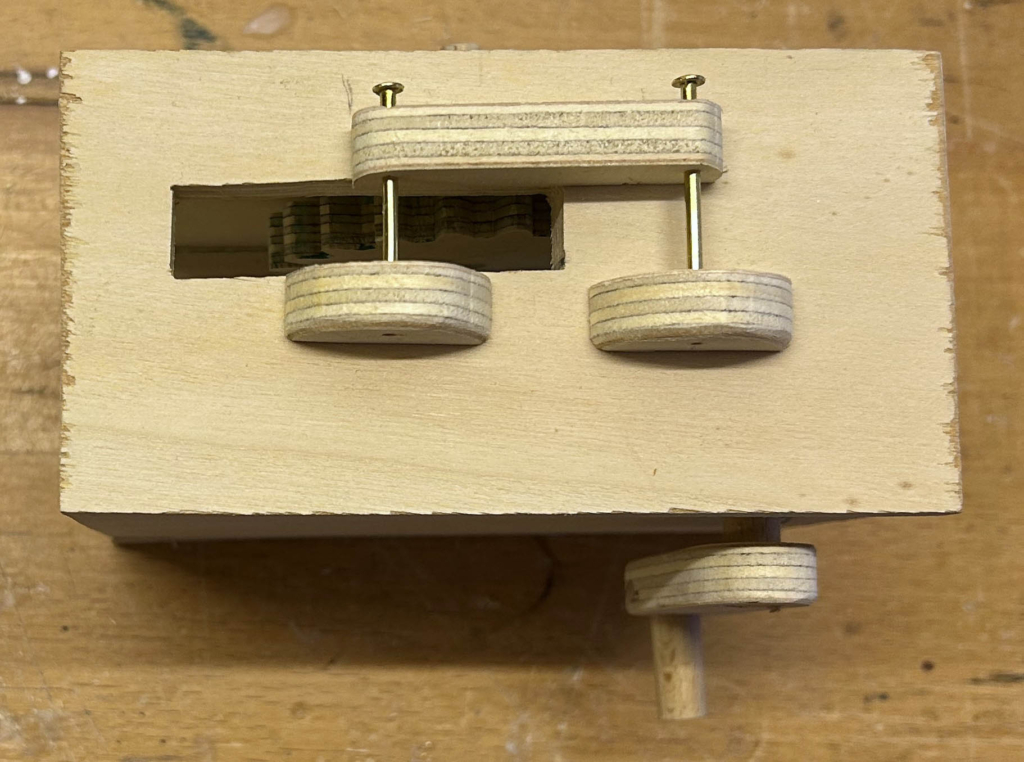
The top of the base
The top holds two brass pins centred in the bear’s feet. The slot is for the lengthened leg which connects to the dowel mounted on the large cogwheel as you can see in the quick prototype assembly.
Rear view full assembly
There is a total of five brass pins for five joints. The legs and the body are move by the cogwheel via the lengthened leg. The arms are firmly attached to the low-hanging head on the front side but the pin passes freely through the body. Gravity thus moves the head and arms to maintain a roughly horizontal position. Friction makes this a bit unpredictable, making the dancing bear’s “moves” more interesting.
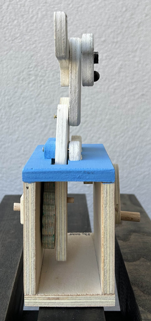
Side view full assembly
From the side, the bear’s shape is not recognisable. As the crank is at the front, this compels a user to look at the front view, which does look like a bear.
Front view full assembly
From the front, it looks satisfyingly bearlike, even if my first young quality control checker reckoned “that’s a funny bear!”. I can’t argue with that.
Reflections
You do have to turn the crank quite quickly to get the bear suitably dancing. Everyone has their own style of dancing of course, so who am I to make the rules? I just used cogs that I found lying around. Should I ever remake this I’d probably use a smaller main cog and speed things up a bit; just a bit, it is a cool bear after all.
I was recently asked to produce some instructions for a moving butterfly using a clothes peg/pin to accompany a small exhibition of automata at the excellent Imaginata museum in Jena, Germany (https://imaginata.de). After the visitors have had fun interacting with the automata on display, the idea is that they should have the opportunity of making their own, very simple automata, on a table in the exhibition space. Obviously it shouldn’t cost too much, whilst showing that it’s not rocket science to get things moving, and that you can use everyday objects which aren’t too hard to find.
Here’s what I came up with.
The Materials
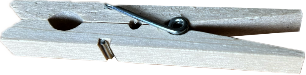
A wooden clothes peg/pin about 7.3 cm long
If your clothes peg is a different size, you may have to scale the pattern to match.
A glue stickColoured felt tip pensA stack of patterns printed on 175 g matt A4 paperScissors
The Pattern
You can download the pattern in PDF format here (ADD LINK), or in JPEG format here (ADD LINK). If you don’t use A4 paper, you could edit the JPEG file to fit on your paper size. The same applies if you want to use a language other than English. When printing, use at least 175 g paper.
Instructions
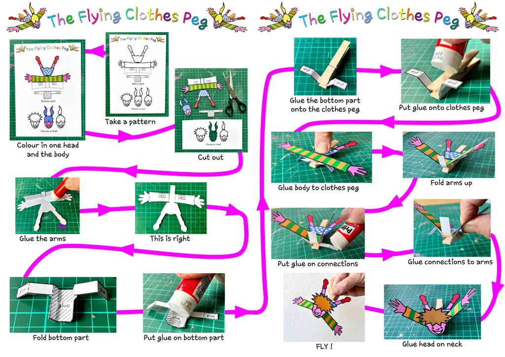
Instructions to make a flying clothes peg
There are two A4 pages of instructions which you can download in PDF formet here (ADD TWO LINKS), or in JPEG format here (ADD TWO LINKS). If you don’t use A4 paper, you could edit the JPEG files to fit on your paper size. The same applies if you want to use a language other than English. Note that I folded the arms to make them stiffer and flap more convincingly.
Testing
Before sending the instructions off to the Imaginata in Jena, I asked a 9 year old to have a go, which she was very happy to do. I had a finished example to show her and she seemed to immediately understand the idea. Colouring in the figure took a while as she considered what her best friend looked like and what colour clothes she wore. Filled with enthusiasm, she wanted to colour in both sides of the A4 pattern, holding the pattern against a window pane to be able to see the pattern through the paper. I then noticed that I should have suggested felt-tip pens instead of the waxy crayons which she had chosen herself. I doubted that the waxy surface would glue properly, so I helped her to avoid the areas where glue was required. She was happy with the finished product and decided to take it to her best friend’s birthday the very next day, together with a kit of parts for her friend to try it out herself.
What Happened to the Butterfly?
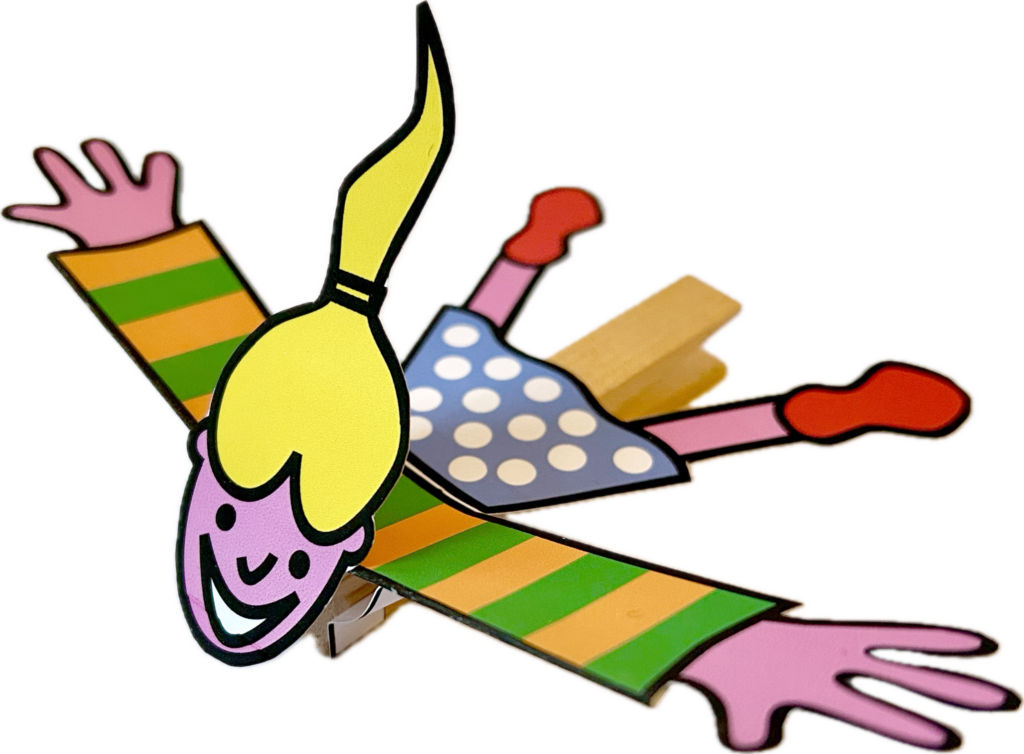
I was asked to make a butterfly, so what happened? Scouring the Internet before starting, to see if someone had already produced instructions, of course I found a video on Youtube. Looking at it, I thought that it was easy to make, if a bit uninteresting. The maker had also used a hot-glue gun which I considered too dangerous and messy for the young or the young at heart to use unsupervised. A glue stick seems to be a good alternative in this case, even if a few seconds of patience is required for it to stick sufficiently. So, I made a flying girl instead of a butterfly and my contact at the museum was happy to accept it, after making one himself to try it out.
The pattern could be modified for all sorts of things. A butterfly, a bat, a dragon, a boy, a bird, a bee, a stingray, a dragonfly anything where flapping is required. I did think about a super-hero, but can you really imagine superman flapping his arms to fly around and save the world? How realistic would that be! What would you make?
Reflections
There is a wide range of automata, that people make using clothes pegs. Often they use bits of wire or straightened paper clips. Sometimes holes are drilled. For this design we don’t need wire cutters or a drill. An all paper design might be possible but I’m guessing that it would be more complicated. A clothes peg is also something very domestic and I think it adds a bit of charm.